The first level-3 automated vehicle is on the road: Is ISO functional safety and analysis in step?
Add bookmark
Because no two automated-driving technologies are exactly alike, SAE International’s standard, J3016, defines six levels of automation, intended to classify a system’s sophistication for use by automakers, suppliers, and policymakers. In this definition a vital change occurs between Levels 2 and 3, when responsibility for monitoring the driving environment shifts from the driver to the system.
The Partial Automation capability of L2 means that the car can steer, accelerate, and brake in certain circumstances, but requires driver involvement to carry out tactical maneuvers such as responding to traffic signals or changing lanes, as does scanning for hazards.
By comparison in the L3, Conditional Automation System the car can manage most aspects of driving, including monitoring the environment and situations that call for an immediate response, such as emergency braking. The driver must, however, still be prepared to intervene when called upon by the vehicle to do so.
The first Level-3 automated vehicle takes to the road
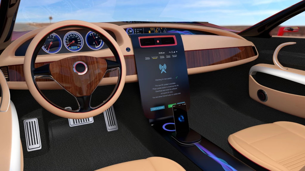
In 2017 Audi launched the world’s first series production L3 conditional automation system - the Audi AI traffic jam pilot, which allows the new A8 to drive in slow-moving highway traffic up to 60 km/h without any input from the driver.
Once the driver activates the traffic jam pilot with the AI button on the center console, they can take their foot off the accelerator and their hands off the steering wheel. Drivers must, however, remain alert and capable of taking over the task of driving when the system prompts them to do so.
The system handles starting from a standstill, accelerating, steering and braking in the lane. It can also react to demanding situations such as vehicles cutting-in in front of the vehicle.
While on paper this may seem fairly straightforward, in practice the technology behind the system is a quantum leap forward in automated driving.
Central to Audi’s Advanced Driver Assistance System Platform is the zFAS control unit, which combines multiple computing tasks on one powerful main board. The most demanding role being sensor fusion where the signals from multiple sensors like stereo cameras, radar, lidar and multi-axis acceleration sensors are merged and transformed into a 360-degree digital environmental model. This in turn is used by all the driver assistance systems including those responsible for autonomous driving to compute their respective actions.
- The zFAS – Produced by Delphi and located under the driver’s seat features four processing chips:
- The Nvidia Tegra K1 is dedicated to processing data from the four cameras used to create a 360-degree surround view of the vehicle when maneuvering in tight spaces
- The Mobileye EyeQ 3, processes the more time-critical data from the stereo front camera and driver monitoring camera, required for L3 automated driving
- The Altera Cyclone V chip with an integrated ARM processor, is used for most of the sensor data fusion
- An Infineon Tricore chip is responsible for making and executing decisions such as planning the vehicle’s trajectory and speed
Furthermore in the zFAS multiple microprocessors and microcontrollers share the workload. Basically, an application processor handles the compute-intensive image processing and low-level data fusion tasks, while the host processor is responsible for the safety-critical aspects like object fusion, decision making and vehicle communication as shown in the block diagram.
The safety-relevant portion of the function is handled by an Aurix multicore microcontroller from Infineon. “You need to differentiate between the computational tasks associated with the graphical procedures and the really safety-critical decision making,” explains Thomas Boehm, Senior Director, Chassis and Safety Microcontrollers at chipmaker Infineon.
For decision-making and communications, the real-time requirements are significantly higher. These tasks have to meet high functional safety standards such as ISO 26262, and the Aurix architecture therefore provides lockstep mechanisms—two identical cores that perform the same computational tasks; if the results do not match, a safety interrupt stops the system.
Furthermore, in mission-critical systems such as autonomous emergency breaking it’s vital that if a fault occurs the system fails-safe, ensuring a safe recovery.
Fail-Safe architecture
Should an automated system fail, manufacturers have two methods to meet the ‘Fail Safe’ requirements that guarantee the continued safe operation of the vehicle:
- In the safety-relevant systems of today’s vehicles, the most common response to a failure is to deactivate or reset the faulty function - this is known as Fail-Silent.
- Fail Silent system development is well covered by ISO 26262. While easy to implement, it is effective in achieving a safe state and preserving it.
- Systems with Fail Operational behavior, on the other hand, maintain full or degraded functionality after a malfunction has been detected.
In higher level automated driving systems it is no longer sufficient to simply deactivate a function to reach a safe state. The safe state has to ensure continued, if reduced, power and functionality. Thus, systems with conditional automation L3 are generally Fail Operational systems, implemented as 1oo2D (one-out-of-two with diagnostics).
In these highly automated systems functional operations must continue in case of a fault - a behavior referred to as Fail Operational with Fault Tolerant capability.
When designing such a system, it is important that the architecture is taken into account for the quantification of the effect of random hardware failures. Usually, a safety system is considered as a serial system of three subsystems: sensor(s), logic solver(s), and final element(s). That is, the system is able to perform its safety function if and only if all these subsystems are able to perform their respective safety sub-functions.
Therefore in Fail-operational/fault tolerant systems it is important that redundancy is engineered into the system. Thus, each subsystem is basically defined by an “M-out-of-N” (MooN) architecture. An M-out-of-N system contains N identical components and works on the principle that if at least M out of N components are functioning correctly, then the system is error-free. Commonly L3 systems are MooND which means they also carry out diagnosis.
Thus, a 1ooN architecture corresponds to a parallel subsystem (the “safest” architecture) and a NooN architecture corresponds to a serial subsystem (the “least safe” architecture).
Another example of this is Triple Modular Redundancy (TMR), which is actually a 2oo3 system. If at least two components (a majority) out of three are working correctly, then the system is considered functional.
Commonly critical components are replicated and on the basis of majority voting, a decision is taken. In SoCs, the redundancy in hardware can take many forms: Replication of cores performing safety critical tasks (a.k.a. Lockstep), delayed lockstep (1oo1 system), asymmetrical lockstep, and Triplevoting (2oo3 system).
In high-level safety compliant devices, the cores performing the safety-critical tasks are also replicated and the applications operate both cores in lockstep mode, comparing the results to make sure the redundant processing yields identical results. If the identical result is not obtained then it is assumed that a fault has occurred.
Furthermore, in lockstep, the same set of inputs is sent to both the cores at the same time, which perform the same calculations in the same clock cycle. The results are compared regularly to detect when a failure, whether transient, intermittent, or permanent, has occurred. On a mismatch in the outputs, generally a fault is flagged and/or a restart is performed.
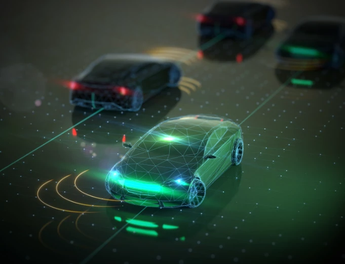
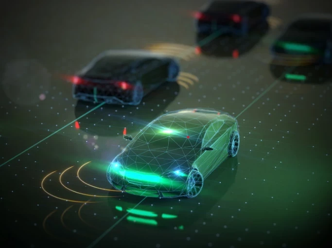
But, while spatial awareness using multiple sensors provides better performance than using a single sensor, it’s vital that all the information gathered is correctly ‘fused’ to guarantee functionally safe operation. This is particularly true in ‘lane-depart’ systems where information gathered from forward and rear facing cameras, radar and lidar are required to work together to enable a safe and smooth transition.
ADAS Sensor and fusion system architecture options
One approach to achieve this, using multiple sensors, is to first perform single sensor tracking and then fuse the tracks from the different sensors.
In this, the data association algorithm plays the vital role of forming an appropriate and valid set of tracks from the available tracks at the fusion center, which are delivered by the different sensors’ local systems. The architecture of the data association module has to be designed taking into account the fusion strategy of the sensor fusion system, the granularity and the quality of the data provided by the sensors.
The figure below shows a functional view of the data flow in a fully equipped sensing and control system for an autonomous vehicle.
On the left are the input sensors, including global positioning (GPS), inertial measurement unit (IMU), cameras, lidar, radar and ultrasound. Each sensor has a certain amount of dedicated sensor processing that processes raw data in order to create an object representation that can be used by the next stage in a hierarchical fusion system.
The conceptual view shown in the figure depicts different types of sensor fusion occurring at various levels. For instance, raw data from a pair of cameras can be fused to extract depth information, a process known as stereo vision. Likewise, data from sensors of different modalities, but with overlapping fields of view, can be fused locally to improve the tasks of object detection and classification.
What's more, object representation provided by on-board sensors, whether originating from a single sensor or via fusion of two or more sensors, can be combined with additional information from nearby vehicles and the infrastructure itself. This information comes from dedicated short-range communication (DSRC), also referred to as vehicle-to-vehicle (V2V) and vehicle-to-infrastructure (V2I) communications. On-board maps and associated cloud-based systems offer additional inputs via cellular communications.
So while Level-3 automated driving is already here it is clear that the complexity of the technology requires that manufacturers fully understand the ISO safety requirements and analysis needed to ensure vehicles operate safely at all times, and in the event of a mission-critical fault are able to fail safe.
Sources:
Christiaan Hetzner; Automotive News Europe; First impressions of Audi's self-driving system; September 2017; http://europe.autonews.com/article/20170909/BLOG15/170909839/first-impressions-of-audis-self-driving-system
Audi Media Center; Audi; Automated driving at a new level: the Audi AI traffic jam pilot; July 2017; https://www.audi-mediacenter.com/en/press-releases/automated-driving-at-a-new-level-the-audi-ai-traffic-jam-pilot-9300
Christoph Hammerschmidt; EETimes; Why Audi’s zFAS Is Blueprint for Next-Gen Domain Architectures; March 2016; https://www.eetimes.com/document.asp?doc_id=1329234
Deepak NegiNeha Bagri,Vikas Agarwal; EDN Network; Redundancy for safety-compliant automotive & other devices; March 2017; https://www.edn.com/Pdf/ViewPdf?contentItemId=4429463
Embedded Vision Aliance; Scalable Electronics Driving Autonomous Vehicle Technologies; https://www.embedded-vision.com/industry-analysis/technical-articles/scalable-electronics-driving-autonomous-vehicle-technologies